In this guideJump to a section
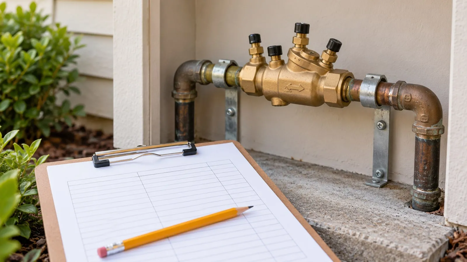
A residential backflow preventer is a mechanical safety valve installed between your potable drinking water supply and auxiliary hazards such as lawn irrigation systems, fire suppression sprinklers, hydronic radiant boilers, or swimming pool auto-fill lines. Under normal hydraulic conditions, water flows in one direction under municipal pressure. When street water pressure drops, reverse flow can siphon fertilizers, weed killers, stagnation bacteria, or antifreeze directly back into household drinking taps.
Maintaining a backflow preventer requires understanding the mechanical operating boundaries of your assembly, calculating hydraulic pressure losses, planning for relief valve water discharge, and maintaining certified annual inspection documentation for the municipal water authority.
Cross connection mechanics and hydraulic backflow risks
Backflow occurs through two distinct hydraulic mechanisms:
- Back-siphonage: Negative or sub-atmospheric pressure in the upstream supply line acts like a vacuum. Common causes include a major water main break down the street, rapid municipal hydrant flushing, or a high-capacity fire department pumper truck drawing hundreds of gallons per minute from the distribution grid. If an outdoor garden hose is submerged in a bucket of liquid fertilizer or a pesticide sprayer tank, back-siphonage sucks the toxic chemical directly backward into the household water pipes.
- Backpressure: Downstream pressure exceeds the upstream municipal supply pressure. This happens when an auxiliary mechanical system—such as a hydronic radiant heating boiler, a booster pump, or an elevated irrigation storage tank—generates pressure higher than street line pressure. If boiler treated water contains chemical rust inhibitors (such as toxic sodium nitrite), backpressure can force contaminated water backward through an unprotected cross-connection into drinking lines.
Federal Safe Drinking Water Act standards and state plumbing codes require physical cross-connection containment assemblies matched to the degree of health hazard.
Hydraulic pressure loss and emergency relief discharge calculations
Installing a testable backflow assembly introduces substantial hydraulic resistance and creates a mechanical discharge path that must be engineered into building plumbing.
1. Calculate continuous dynamic pressure loss
A Reduced Pressure Zone (RPZ) assembly contains heavy internal stainless steel springs holding the check poppets against their seats, creating an inherent pressure drop:
Total Dynamic Pressure Drop = Check Valve 1 Drop + Check Valve 2 Drop + Valve Body Friction
- First check valve (CV1): Requires a minimum cracking differential pressure of 5.0 psi (typically designed to drop 6.0 to 8.0 psid under flow conditions).
- Second check valve (CV2): Requires a minimum cracking differential pressure of 1.0 psid.
- Body and shutoff friction: Turbulence through the bronze valve body and two full-port isolation ball valves adds 2.0 to 4.0 psi depending on flow rate.
For example, a typical residential lawn irrigation zone operating at 15 GPM (gallons per minute) through a 1-inch RPZ assembly experiences:
Total Dynamic Drop = 6.5 psi (CV1) + 1.5 psi (CV2) + 3.2 psi (Friction) = 11.2 psi total drop
If your incoming street water pressure is 50.0 psi, dynamic pressure available at your sprinkler zone valves drops to:
50.0 psi - 11.2 psi = 38.8 psi available operating pressure
Sprinkler nozzles calibrated for 45 psi will produce reduced throw distance and dry lawn rings unless the irrigation system was specifically hydraulic-modeled with this 11 psi backflow loss.
2. Sizing emergency relief valve discharge capacity
An RPZ assembly is fail-safe because its differential pressure relief valve opens to atmosphere whenever the pressure difference between the supply and the intermediate chamber drops below 2.0 psid.
If a piece of rust, mineral scale, or sand lodges under the seat of Check Valve 1 during a back-siphonage event, the relief valve dumps water at high volume. Under standard line pressure (60 psi), a 1-inch RPZ relief valve discharges up to 35 GPM of water:
Catastrophic Discharge Rate = 35 GPM × 60 min/hr = 2,100 gallons per hour
Installing an RPZ in a finished basement, crawlspace, or un-drained utility room without an indirect waste air-gap drain can flood an entire home within hours. Plumbing codes mandate that any indoor RPZ must be fitted with an air-gap funnel and routed via gravity drain piping to an outdoor daylit drainage swale or high-capacity floor drain capable of handling the maximum rated discharge rate.
Backflow assembly selection and engineering matrix
| Backflow Assembly Classification | Applicable ASSE Standard | Hazard Protection Level | Allowable Hydraulic Conditions | Fails When / Freeze & Pressure-Drop Limits |
|---|---|---|---|---|
| Reduced Pressure Zone (RPZ) | ASSE 1013 / CSA B64.4 | High Health Hazard (Chemicals, toxic fertilizers, boilers) | Continuous pressure, back-siphonage, and backpressure | High pressure drop (8 to 14 psi); relief valve dumps up to 35 GPM during foul; splits under outdoor freeze without heat tape; forbidden in pits |
| Double Check Valve Assembly (DCVA) | ASSE 1015 / CSA B64.5 | Low / Non-Health Hazard (Aesthetic pollutants, food service) | Continuous pressure, back-siphonage, and backpressure | Moderate pressure drop (3 to 6 psi); ILLEGAL for toxic chemicals or chemical fertilizers; lacks relief vent (fails unobserved); freeze ruptures ball valves |
| Pressure Vacuum Breaker (PVB) | ASSE 1020 / CSA B64.1.2 | High or Low Hazard (Irrigation sprinkler zones) | Continuous pressure, Back-siphonage ONLY (No backpressure) | Low pressure drop (2 to 5 psi); FAILS CATASTROPHICALLY under backpressure; must be installed >= 12 in above highest downstream sprinkler head |
| Atmospheric Vacuum Breaker (AVB) | ASSE 1001 / CSA B64.1.1 | High or Low Hazard (Hose bibbs, mop sinks, single fixtures) | Intermittent flow (< 12 hrs continuous), Back-siphonage ONLY | Negligible pressure drop (< 2 psi); non-testable device; cannot be subjected to continuous pressure; fails if downstream shutoff valve is added |
Annual certified testing requirements and field recordkeeping
Because backflow prevention assemblies contain mechanical springs, elastomeric rubber discs, and moving diaphragms, mineral deposits and fatigue will inevitably degrade their performance over time. Municipal water providers mandate certified field testing at initial installation, after any repair or relocation, and at least annually thereafter.
Testing must be conducted by an ASSE 5110 or ABPA-certified backflow prevention assembly tester using a calibrated five-valve differential pressure test gauge:
- Test Cock 1 to 4 connection: The tester connects high, low, and vent hoses to the assembly’s four diagnostic needle test cocks.
- Relief valve opening differential test: Verifies that the RPZ relief valve opens before the differential pressure between supply and intermediate zone drops below 2.0 psid.
- Check Valve 2 tight-seating test: Confirms Check Valve 2 holds tight against backpressure without back-leakage into the intermediate zone.
- Check Valve 1 cracking pressure test: Confirms Check Valve 1 maintains at least 5.0 psid differential across its disc.
Keep a permanent household backflow record binder containing:
- Device manufacturer, exact model number, pipe diameter size, and factory serial number.
- Installation date, original plumbing permit number, and physical property location.
- Annual signed certified test inspection reports with differential pressure readings.
- Tester’s license number, certification agency, and test kit calibration verification date.
- Maintenance receipts documenting rubber rebuild kits (replacing O-rings, check springs, and diaphragms every 3 to 5 years).
- Copy of the formal compliance submission confirmation receipt sent to the local water purveyor.
Winter freeze winterization and relief drainage guidelines
In temperate climates, exterior backflow assemblies connected to residential lawn sprinkler systems are exceptionally vulnerable to winter freeze damage. Because backflow assemblies are mounted above ground level—PVBs must sit at least 12 inches above the highest sprinkler head, and RPZs must sit at least 12 inches above grade—they have zero thermal protection from frozen soil. Water freezing inside the assembly expands by 9%, cracking expensive bronze casting bodies and warping stainless check springs.
Follow the four-step winterization shutdown sequence before the first seasonal hard frost (below 32°F / 0°C):
- Isolate the interior water supply: Locate the dedicated indoor shutoff ball valve feeding the outdoor backflow assembly (typically in the basement or utility closet). Close this valve completely. Open the small knurled bleeder cap on the side of the indoor valve body to drain standing water trapped in the pipe section passing through the exterior wall.
- Execute compressed air blowout: Connect a high-volume air compressor (minimum 10 to 15 CFM at an air pressure regulated strictly below 50 psi) to the irrigation blowout port downstream of the backflow assembly. Never blow compressed air directly backward through an RPZ or PVB assembly; excessive air velocity spins internal plastic poppets off their guides and melts delicate rubber check seats.
- Leave isolation ball valves at a 45-degree angle: This step is the single most common homeowner oversight. Standard quarter-turn brass ball valves trap a spherical pocket of water between the chrome ball and the valve casing when left fully open or fully closed. When that trapped water freezes, it splits the valve body along the side seam. Turn both upstream and downstream isolation ball valves to a 45-degree half-open position, and open all four diagnostic test cocks to 45 degrees with a flathead screwdriver to allow water expansion clearance.
- Insulate or remove for winter: If your local plumbing code permits quick-disconnect unions, unthread the entire bronze assembly, label the port orientation, and store it indoors in a heated basement or garage for the winter. If the assembly is permanently sweated into copper piping, wrap the brass body in closed-cell elastomeric foam pipe insulation and enclose it inside an insulated fiberglass protective hot-box (meeting ASSE 1060 Class 1 or Class 2 specifications).
Maintaining an accurate device inspection log and winterizing on schedule prevents emergency cross-connection shutoffs by the water authority and eliminates costly springtime bronze valve replacements.
- Confirm the indoor isolation ball valve feeding the exterior backflow assembly is completely closed before the first seasonal freeze.
- Verify that both the upstream and downstream brass isolation ball valves on the assembly are turned to a 45-degree angle.
- Check that all four diagnostic test cocks are opened to a 45-degree position using a flathead screwdriver to prevent trapped water expansion.
- Ensure the small knurled bleeder cap on the indoor shutoff valve is opened to drain any water remaining in the wall penetration pipe.
- Inspect the physical record binder to confirm the annual certified inspection report has been successfully submitted to the municipal water purveyor.
The physics of water expansion during freezing dictates that rigid bronze and brass plumbing components cannot survive the 9% volumetric increase of turning to ice. When ambient air temperatures drop below 32°F (0°C) for several consecutive hours, the stationary water trapped inside a backflow assembly begins to crystallize. Standard quarter-turn brass ball valves are particularly susceptible because their design creates a sealed spherical cavity between the chrome ball and the outer brass casing when the valve handle is parallel (fully open) or perpendicular (fully closed). If this trapped water freezes, the resulting hydraulic pressure easily exceeds the tensile strength of the cast brass, shearing the valve body along its manufacturing seam. Positioning the handles at exactly 45 degrees breaks this hydraulic seal, allowing the expanding ice to extrude harmlessly into the main pipe cavity.
relying solely on air blowout procedures without addressing the diagnostic test cocks guarantees failure. The four small needle valves protruding from the side of a testable assembly each contain a miniature internal ball valve. Even if the main chamber is blown dry with compressed air, capillary action retains a few drops of water inside these test cocks. When frozen, this minuscule amount of water destroys the delicate internal seating surfaces, rendering the entire assembly untestable the following spring. Municipal water authorities strictly enforce the functionality of these test cocks, as they are the only mechanism an inspector can use to measure the internal differential pressure of the check valves. A failed test cock necessitates the replacement of the entire backflow unit, costing hundreds of dollars in parts and certified labor. Strict adherence to these physical shutdown steps preserves the mechanical integrity of the cross-connection control device and ensures continuous compliance with safe drinking water regulations. For emergency drinking water planning while exterior plumbing is winterized or undergoing inspection, check the emergency water safety guide and use the water storage calculator to ensure continuous household reserves.